Degree
of fuzzification:
The degree of fuzzification is determined by the number of Fuzzy Labels,
which are used to describe a system using fuzzy rules. These labels
may take forms such as Negative Large (NL), Zero(ZE), Positive Large(PL)
etc. Seven is generally considered to the optimum number of fuzzy labels
implemented in a fuzzy rule system. The scheme adopted in our design
uses 7 labels starting from NL at 2.5V and concluding with PL at 8.5V
where each label within is 1V away from its neighbour (fig. 5). Back
to top
Active
Rules: The number of
rules required for a fuzzy processor is R =L^I where the number of rules
is denoted by R, and the number of fuzzy labels by L and the number
of inputs by I. However, at any given time, the majority of rules are
idle. Implementation of all rules would therefore lead to redundancy
and silicon wastage. Active rules are those that produce a non-zero
contribution. The maximum number of active rules (MAR) at any instant
is MAR = ( 2 )^ I Back
to top
Rule
Circuits:
With the reduction of the number of rule circuits to MAR, the
number of expected active rules of a particular rule set will always
be even. Therefore, our design uses a sub-system of 2-rule aggregation,
consisting of 4 Membership Function Circuits (MFC) where each rule utilises
2 MFCs. MFCs that are not triggered by any fired rules are switched
off by setting their bias currents to zero, removing their contribution
to the output. Back
to top
Programmability:
The ability to share this minimum number of rule circuits relies greatly
on their programmability. This is easily achieved using digital modules
to instruct each rule circuit of its antecedent triggered rule label,
and to generate labels in the consequent by multiplying each normalised
rule weight. Back
to top
Implementation:
The architecture of the proposed design is shown.
The centre of gravity stage is implemented using the Normalisation Lock
Loop (NLL) technique, which enables the parallel distribution of fuzzy
rules to be aggregated instantaneously. Current mode modules are interfaced
with ease. Circuit complexity can be further reduced by inverting the
membership function, so that a MAX circuit is used, instead of a MIN
circuit, in the antecedent. In order to perform inference processing
of the algorithm in eqn 1, a truth level is defined for each rule i:
Itruth(i) = max( Ai (a), Bi (b) ). Itruth(i) is then normalised by the
weight circuit to Iw(i) through a feedback control voltage. The normalised
consequent contribution of each rule Iw(i) is multiplied by the weight
label Xi of each rule to give the contribution of that particular rule
xi. xi = Iw(i) Xi. The NLL computes the centre of gravity by summing
n normalised, and weighted currents:

Back
to top
Proposed
architecture of the fuzzy processor

Back
to top
The
inverted membership function generatot and weight circuit

Back
to top
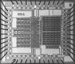
Fuzzy
inference processor layout
Back
to top