|
|
![]()

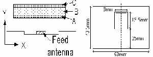
A small H shape quarter wave
patch antenna with an area reduction of 3.3 times compared to the quarter
wave patch is used as the feed antenna
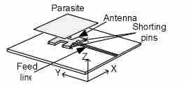
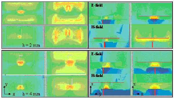
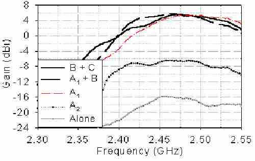
The experimental setup of this configuration is shown above. The antenna is designed over a ground of 80 x 80 mm, with a gain of -16dBi. The tuned parasite measuring 48 x 53 mm is then placed above the feed antenna. Other configuration of parasite used are shown below.
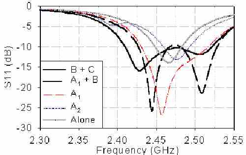
Parasite configuration: A - First parasite A1 = Tuned at 48 x 53 (mm); or A2 = 0.5l at 60 x 60 (mm); B - dielectric layer (FR4, thickness 0.508mm) on first parasite; C - Parasite 43.5 x 53 (mm) with U-Slot printed